Shear and Bending Moment Diagram :
The shear force diagram indicates the shear force withstood by the beam section along the length of the beam.
The bending moment diagram indicates the bending moment withstood by the beam section along the length of the beam.
It is normal practice to produce a free body diagram with the shear diagram and the bending moment diagram position below
For simply supported beams the reactions are generally simple forces. When the beam is built-in the free body diagram will show the relevant support point as a reaction force and a reaction moment....
Sign Convention
The sign convention used for shear force diagrams and bending moments is only important in that it should be used consistently throughout a project. The sign convention used on this page .
Shearing Force :
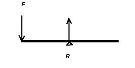
The shearing force (SF) at any section of a beam represents the tendency for the portion of the beam on one side of the section to slide or shear laterally relative to the other portion.
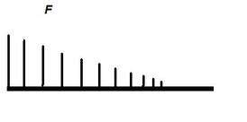
The diagram shows a beam carrying loads . It is simply supported at two points where the reactions are Assume that the beam is divided into two parts by a section XX The resultant of the loads and reaction acting on the left of AA is F vertically upwards and since the whole beam is in equilibrium, the resultant force to the right of AA must be F downwards. F is called the Shearing Force at the section AA. It may be defined as follows:-
The shearing force at any section of a beam is the algebraic sum of the lateral components of the forces acting on either side of the section.
Where forces are neither in the lateral or axial direction they must be resolved in the usual way and only the lateral components use to calculate the shear force.
Bending Moment :
In a similar manner it can that if the Bending moments (BM) of the forces to the left of AA are clockwise then the bending moment of the forces to the right of AA must be anticlockwise.
Bending Moment at AA is defined as the algebraic sum of the moments about the section of all forces acting on either side of the section
Bending moments are considered positive when the moment on the left portion is clockwise and on the right anticlockwise. This is referred to as a sagging bending moment as it tends to make the beam concave upwards at AA. A negative bending moment is termed hogging.
Type of Loads :
A beam is normally horizontal and the loads vertical. Other cases which occur are considered to be exceptions.
A Concentrated Load
Is one which can be considered to act at a point although of course in practice it must be distributed over a small area like weight or reactions .
A Distributed Load
is one which is spread in some manner over the length or a significant length of the beam. It is usually quoted at a weight per unit length of beam. It may either be uniform or vary from point to point.
Example Of Diagrams :
A shear force diagram is simply constructed by moving a section along the beam from (say)the left origin and summing the forces to the left of the section. The equilibrium condition states that the forces on either side of a section balance and therefore the resisting shear force of the section is obtained by this simple operation
The bending moment diagram is obtained in the same way except that the moment is the sum of the product of each force and its distance(x) from the section. Distributed loads are calculated buy summing the product of the total force (to the left of the section) and the distance(x) of the centroid of the distributed load.
The sketches below show simply supported beams with on concentrated force.
Drawing of Shear Force and Bending Moment Diagrams:
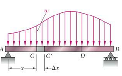
Consider a simple beam shown of length L that carries a uniform load of w (N/m) throughout its length and is held in equilibrium by reactions R1 and R2. Assume that the beam is cut at point C a distance of x from the left hand support and the portion of the beam to the right of C be removed. The portion removed must then be replaced by vertical shearing force V together with a couple M to hold the left portion of the bar in equilibrium under the action of R1 and wx.
Write shear and moment equations for the beams in the following problems. In each problem, let x be the distance measured from left end of the beam to the point under study. Also, draw shear and moment diagrams, specifying values at all change of loading positions and at points of zero shear. Neglect the mass of the beam in each problem.
The vertical shear at C will be
VC=R1–wx (Linear variation)
Where R1 = R2 = wL/2
Vc=wL/2−wx
The moment at C is
MC= (wL/2)x−wx x/2
MC=wLx/2−wx2/2 (Parabolic variation)
If we differentiate M with respect to x:
dM/dx=wL/2 − wx=shear force at x
thus, dM/dx =Vx
Thus, the rate of change of the bending moment with respect to x is equal to the shearing force
RELATION BETWEEN BENDING MOMENT AND SHEAR FORCE: The slope of the bending moment diagram at the given point is the shear force at that point.
dM/dx =Vx
RELATION BETWEEN SHEAR FORCE and UDL: Differentiate V with respect to x gives dV/dx=0−w
thus, dV/dx =-UDL= -w
dV/dx =-w
Thus, the rate of change of the shearing force with respect to x is equal to the load (UDL)
Properties of Shear Force and Bending Moment Diagrams .
The following are some important properties of shear and moment diagrams:
1. The area of the shear diagram to the left or to the right of the section is equal to the moment at that section.
2. The slope of the moment diagram at a given point is the shear force at that point.
3. The slope of the shear diagram at a given point equals the -UDL at that point.
4. The maximum moment occurs at the point of zero shear. When the shear is zero, the slope of moment diagram is zero. Hence tangent drawn to the moment diagram is horizontal.
5. When the shear force is increasing, the moment diagram is concave upward.
6. When the shear force is decreasing, the moment diagram is concave downward.
Relations among Load, Shear, and Bending Moment:
When a beam carries more than two or three concentrated loads, or when it carries distributed loads, the method for plotting shear and bending moment can prove cumbersome. The construction of the shear diagram and, especially, of the bending-moment diagram will be greatly facilitated if certain relations existing among load, shear, and bending moment are taken into consideration.
Relations between Load and Shear:
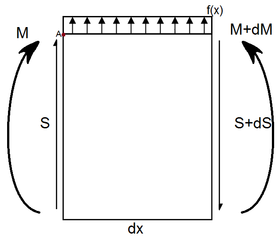
∑Fy ↑=0=S-(S+dS)+F dx
0=S-S-dS+Fdx
F=dS/dx
S=ʃ F dx
∑MA=0=M-(M+dM)+(S+dS)-F dx (dx/2)
-dM+S dx + dS dx- (F dx dx )/2=0
dM/dx=S
M=ʃ S dx = ʃʃ F dx
0=S-S-dS+Fdx
F=dS/dx
S=ʃ F dx
∑MA=0=M-(M+dM)+(S+dS)-F dx (dx/2)
-dM+S dx + dS dx- (F dx dx )/2=0
dM/dx=S
M=ʃ S dx = ʃʃ F dx
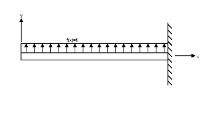
S=ʃ F dx =ʃ F0 dx
=F0 x+ C1
S=F0 x
M=ʃ S dx=ʃ F0x dx= F0 x2/2 +C2
M=(F0 x2)/2
Fy=F0L
Mz= (F0 L2)/2
S(L)=0 è F0L+C1=0
Then C1= - F0 L
Fy=F0 L
S+F0L=0 è S=-F0 L
M=ʃ S dx =ʃ (F0 x-F0 L)dx=(F0 x2)/2 – F0 L x + C2
At x=L è M=0
0=(F0 L2)/2 – F0 L2 + C2 è C2=(F0 L2)/2
=F0 x+ C1
S=F0 x
M=ʃ S dx=ʃ F0x dx= F0 x2/2 +C2
M=(F0 x2)/2
Fy=F0L
Mz= (F0 L2)/2
S(L)=0 è F0L+C1=0
Then C1= - F0 L
Fy=F0 L
S+F0L=0 è S=-F0 L
M=ʃ S dx =ʃ (F0 x-F0 L)dx=(F0 x2)/2 – F0 L x + C2
At x=L è M=0
0=(F0 L2)/2 – F0 L2 + C2 è C2=(F0 L2)/2
