Stress and strain at a point in a solid are defined with respect to an arbitrary coordinate
system, e.g. the orientation of a strain gauge. The values of the 6 components of stress or
strain change as this coordinate system is rotated. It is often necessary to perform this
rotation transformation between 2 general coordinate systems or to determine the
magnitudes and orientation of the principal stress and strain components.
Stress transformation between 2 arbitrary coordinate systems:
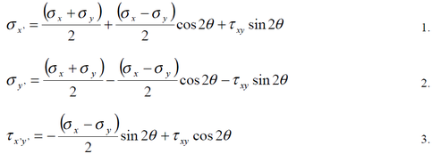
If Ơx, Ơy and txy are the 2 dimensional stress components on the faces of a stress element
aligned with the xy coordinate system, then the stress components Ơx’, Ơy’ and tx’y’ with
respect to an element aligned with the x’y’ coordinate system, rotated by angle Ɵ from xy
are:
system, e.g. the orientation of a strain gauge. The values of the 6 components of stress or
strain change as this coordinate system is rotated. It is often necessary to perform this
rotation transformation between 2 general coordinate systems or to determine the
magnitudes and orientation of the principal stress and strain components.
Stress transformation between 2 arbitrary coordinate systems:
If Ơx, Ơy and txy are the 2 dimensional stress components on the faces of a stress element
aligned with the xy coordinate system, then the stress components Ơx’, Ơy’ and tx’y’ with
respect to an element aligned with the x’y’ coordinate system, rotated by angle Ɵ from xy
are:
Note that, if we add equations 1 and 2 we get:
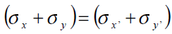
i.e. the sum of the normal stress components is invariant under
this rotation transformation.
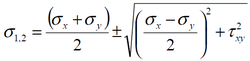
We can determine the maximum and minimum values of the stress components by
differentiating these equations with respect to Ɵ . For the normal stress components the
result is the principal stresses:
this rotation transformation.
We can determine the maximum and minimum values of the stress components by
differentiating these equations with respect to Ɵ . For the normal stress components the
result is the principal stresses:
The angle of rotation Ɵ1 from the xy directions to the principal directions is:
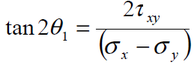
If this value of Ɵ is substituted into Eq. 3 above we find that txy = 0, i.e. the shear stress
components are zero on the faces of the principal stress element.
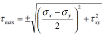
The maximum value of the shear stress component is found on an element rotated by
angle Ɵ2 from the xy direction, where Ɵ2= Ɵ1+ 45o. The maximum shear stress is:
components are zero on the faces of the principal stress element.
The maximum value of the shear stress component is found on an element rotated by
angle Ɵ2 from the xy direction, where Ɵ2= Ɵ1+ 45o. The maximum shear stress is:
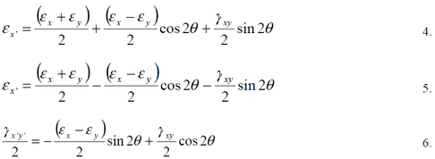
Strain transformation between 2 arbitrary coordinate systems:
If ex, ey and gxy are the 2 dimensional strain components on the faces of a strain element
aligned with the xy coordinate system, then the strain components ex’, ey’ and gx’y’ with
respect to an element aligned with the x’y’ coordinate system, rotated by angle Ɵ from xy
are:
If ex, ey and gxy are the 2 dimensional strain components on the faces of a strain element
aligned with the xy coordinate system, then the strain components ex’, ey’ and gx’y’ with
respect to an element aligned with the x’y’ coordinate system, rotated by angle Ɵ from xy
are:
Note that, if we add equations 4 and 5 we get :
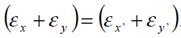
i.e. the sum of the normal strain components is invariant under this
rotation transformation.
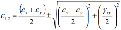
We can determine the maximum and minimum values of the strain components by
differentiating these equations with respect to Ɵ. For the normal strain components the
result is the principal strains:
rotation transformation.
We can determine the maximum and minimum values of the strain components by
differentiating these equations with respect to Ɵ. For the normal strain components the
result is the principal strains:
The angle of rotation Ɵ1 from the xy directions to the principal directions is:
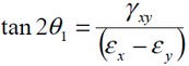
If this value of Ɵ is substituted into Eq. 3 above we find that txy = 0, i.e. the shear strain
components are zero on the faces of the principal strain element.
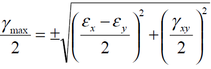
The maximum value of the shear strain component is found on an element rotated by
angle Ɵ2 from the xy direction, where Ɵ1= Ɵ2+45 . The maximum shear strain is:
components are zero on the faces of the principal strain element.
The maximum value of the shear strain component is found on an element rotated by
angle Ɵ2 from the xy direction, where Ɵ1= Ɵ2+45 . The maximum shear strain is:
Note that the strain transformation equations are almost identical in form to those for
stress transformation. The normal stress components are replaced by the normal strain
components and the shear stress components are replaced by the shear strain components
divided by two.
stress transformation. The normal stress components are replaced by the normal strain
components and the shear stress components are replaced by the shear strain components
divided by two.
