Bending :
In This Page, we will discuss the following points
▶ Explaining axial, shear, and moments as internal forces
▶ Computing internal forces at a point
▶ Developing generalized internal force equations
▶ Drawing shear and moment diagrams
▶pure bending
In This Page, we will discuss the following points
▶ Explaining axial, shear, and moments as internal forces
▶ Computing internal forces at a point
▶ Developing generalized internal force equations
▶ Drawing shear and moment diagrams
▶pure bending
For many engineers, the ability to analyze the internal forces of bending members is probably one of the most important skills that you can develop, partly because many structures and objects in the real world aren’t just axially loaded. In fact, the beams in the floor you’re sitting on (assuming it’s not the ground floor) or even the rafters in your roof are all examples of bending members.
Bending is a process by which metal can be deformed by plastically deforming the material and changing its shape. The material is stressed beyond the yield strength but below the ultimate tensile strength. The surface area of the material does not change much. Bending usually refers to deformation about one axis.
truss systems, which are comprised of members subjected to only axial internal forces, which cause a member to become longer in tension and shorter in compression . But what happens when a member isn’t loaded with just an axial load? Figure 20-1 also shows a point load that is acting perpendicular to the member’s longitudinal axis. When this type of member (also known as a bending member) is loaded, it wants to deflect in the direction of the applied load, but not in the direction of the longitudinal axis of the member. As a result, axial tension or compression are no longer the only forces that appear internally
Free-body diagrams
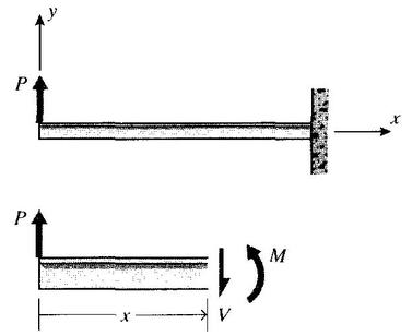
As a simple starting example, consider a beam clamped (\cantilevered") at one end and subjected
to a load P at the free end as shown in Fig. 2. A free body diagram of a section cut
transversely at position x shows that a shear force V and a moment M must exist on the cut
section to maintain equilibrium.these are the resultants of shear and normal stresses that are set up on internal planes by the bending loads. As usual, we will consider section areas whose normals point in the +x direction to be positive; then shear forces pointing in the +y direction on +x faces will be considered positive. Moments whose vector direction as given by the right-hand rule are in the +z direction (vector out of the plane of the paper, or tending to cause counterclockwise rotation in the plane of the paper) will be positive when acting on +x faces. Another way to recognize positive bending moments is that they cause
the bending shape to be concave upward. For this example beam, the statics equations give:
Bending is a process by which metal can be deformed by plastically deforming the material and changing its shape. The material is stressed beyond the yield strength but below the ultimate tensile strength. The surface area of the material does not change much. Bending usually refers to deformation about one axis.
truss systems, which are comprised of members subjected to only axial internal forces, which cause a member to become longer in tension and shorter in compression . But what happens when a member isn’t loaded with just an axial load? Figure 20-1 also shows a point load that is acting perpendicular to the member’s longitudinal axis. When this type of member (also known as a bending member) is loaded, it wants to deflect in the direction of the applied load, but not in the direction of the longitudinal axis of the member. As a result, axial tension or compression are no longer the only forces that appear internally
Free-body diagrams
As a simple starting example, consider a beam clamped (\cantilevered") at one end and subjected
to a load P at the free end as shown in Fig. 2. A free body diagram of a section cut
transversely at position x shows that a shear force V and a moment M must exist on the cut
section to maintain equilibrium.these are the resultants of shear and normal stresses that are set up on internal planes by the bending loads. As usual, we will consider section areas whose normals point in the +x direction to be positive; then shear forces pointing in the +y direction on +x faces will be considered positive. Moments whose vector direction as given by the right-hand rule are in the +z direction (vector out of the plane of the paper, or tending to cause counterclockwise rotation in the plane of the paper) will be positive when acting on +x faces. Another way to recognize positive bending moments is that they cause
the bending shape to be concave upward. For this example beam, the statics equations give:
∑Fy = 0 = V +P --> V = constant = -P (1)
∑M0 = 0 = -M +Px -->M = M(x) = Px (2)
Note that the moment increases with distance from the loaded end, so the magnitude of the
maximum value of M compared with V increases as the beam becomes longer. This is true of
most beams, so shear effects are usually more important in beams with small length-to-height
ratios.
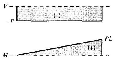
As stated earlier, the stresses and deflections will be shown to be functions of V and M, so it
is important to be able to compute how these quantities vary along the beam's length. Plots of
V (x) andM(x) are known as shear and bending moment diagrams, and it is necessary to obtain
them before the stresses can be determined. For the end-loaded cantilever, the diagrams shown
in Fig. 3 are obvious from Eqns. 1 and 2.
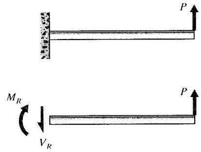
F igure 4: Wall reactions for the cantilevered beam
It was easiest to analyze the cantilevered beam by beginning at the free end, but the choice
of origin is arbitrary. It is not always possible to guess the easiest way to proceed, so consider
what would have happened if the origin were placed at the wall as in Fig. 4. Now when a free
body diagram is constructed, forces must be placed at the origin to replace the reactions that
were imposed by the wall to keep the beam in equilibrium with the applied load. These reactions
can be determined from free-body diagrams of the beam as a whole (if the beam is statically
determinate), and must be found before the problem can proceed. For the beam of Fig. 4:
∑Fy = 0 = -VR+P àVR = P
∑Mo = 0 =MR -PL àMR = PL
The shear and bending moment at x are then
V (x) = VR = P = constant
M(x) =MR -VRx = PL-Px
This choice of origin produces some extra algebra, but the V (x) and M(x) diagrams shown in
Fig. 5 are the same as before (except for changes of sign): V is constant and equal to P, andM
varies linearly from zero at the free end to PL at the wall.
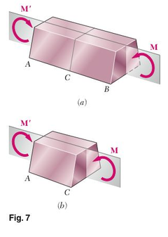
2. Symmetric member in pure bending
Consider a prismatic member AB possessing a plane of symmetry and subjected to equal and opposite couples M and M' acting in that plane (Fig. 7a). We observe that if a section is passed through the member AB at some arbitrary point C, the conditions of equilibrium of the portion AC of the member require that the internal forces in the section be equivalent to the couple M (Fig. 7b). Thus, the internal forces in any cross section of a symmetric member in pure bending are equivalent to a couple. The moment M of that couple is referred to as the bending moment in the section. Following the usual convention, a positive sign will be assigned to M when the member is bent as shown in Fig. 7a, i.e., when the concavity of the beam faces upward, and a negative sign otherwise.
Denoting by Ơx the normal stress at a given point of the cross section and by τxy and τxz the components of the shearing stress, we express that the system of the elementary internal forces exerted on the section is equivalent to the couple M (Fig. 8).
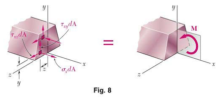
We recall from statics that a couple M actually consists of two equal and opposite forces. The sum of the components of these forces in any direction is therefore equal to zero. Moreover, the moment of the couple is the same about any axis perpendicular to its plane, and is zero about any axis contained in that plane. Selecting arbitrarily the z axis as shown in Fig. 8, we express the equivalency of the elementary internal forces and of the couple M by writing that the sums of the components and of the moments of the elementary forces are equal to the corresponding components and moments of the couple M:
X components: ʃƠx dA =0 ... (1)
Moments about y axis: ʃƠx dA=0 … (2)
Moments about z axis: ʃ(-yƠx dA)=M … (3)
Three additional equations could be obtained by setting equal to zero the sums of the y components, z components, z components, and moments about the x-axis, but these equations would involve only the components of the shearing stress and, as you will see in the next section, the components of the shearing stress are both equal to zero.
Two remarks should be made at this point: (1) The minus sign in Eqn. (3) is due to the fact that a tensile stress (Ơx 0) leads to a negative moment (clockwise) of the normal force Ơx dA about the z axis. Couples in the plane of symmetry of member AB will result in a distribution of normal stresses that is symmetric about the y axis.
Once more, we note that the actual distribution of stresses in a given cross section cannot be determined from statics alone. It is statically indeterminate and may be obtained only by analyzing the deformations produced in the member.
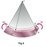
3. Deformations in a symmetric member in pure bending:
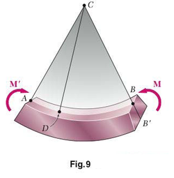
Let us now analyze the deformations of a prismatic member possessing a plane of symmetry and subjected at its ends to equal and opposite couples M and M' acting in the plane of symmetry. The member will bend under the action of the couples, but will remain symmetric with respect to that plane (Fig. 9). Moreover, since the bending moment M is the same in any cross section, the member will bend uniformly. Thus, the line along which the upper face or the member intersects the plane of the couples will have a constant curvature. In other words, the line AB, which was originally a straight line, will be transformed into a circle of center C, and so will the line A'B' (not shown in the figure) along which the lower face of the member intersects the plane of symmetry. We also note that the line AB will decrease in length when the member is bent as shown in the figure, i.e., when M 0 , while A'B' will become longer.
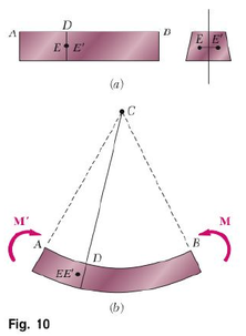
Next we will prove that any cross section perpendiculars to the axis of the member remain plane, and that the plane of the section passes through C. If this were not the case, we could find a point E of the original section through D (Fig. 10a) which, after the member has been bent, would not lie in the plane perpendicular to the plane of symmetry that contains line CD (Fig. 10b) .But because of the symmetry of the member , there would be another point E' that would be transformed exactly in the same way. Let us assume that, After the beam has been bent, both points would be located to the left of the plane defined by CD, As shown in Fig. 10b. Since the bending moment M is the same throughout the member, A similar situation would be prevail in any other cross section, and the points corresponding to E and E' would also move to the left. Thus, an observer at A would conclude that the loading causes the points E and E' in the various cross sections to move forward. But an observer at B, to whom the loading looks the same, and who observes the points E and E' in the same positions would reach the opposite conclusion. This inconsistency leads us to conclude that E and E' will lie in the plane defined by CD and, therefore that section remains plane and passes through C. We should note, however, that this discussion doesn't rule out the possibility of deformations within the plane of the section.
